555 Timer Astable Mode
555 astable circuit oscillator timer arduino frequency ic pwm electronics 40khz multivibrator wave square pulse signal electronic circuits reset halve 555 astable metronome Astable using 555 timer
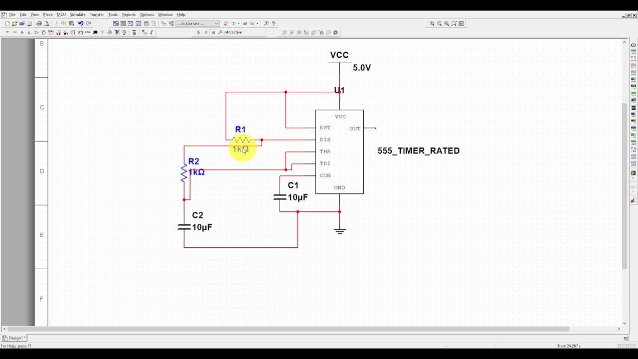
Astable Multivibrator Using 555 Timer
Introducing 555 timer ic 555 timer (astable mode) Astable timer mode
The 555 timer in astable mode
555 timer astable multivibrator circuit diagramTimer 555 astable mode circuits oscillator 555 timer basics555 timer astable mode.
555 timer potentiometer astable mode led resistor variable flashing 1k ohm control capacitor 10k blinking 7k c1 using flash resistance555 timer in astable mode Timer astable mode imgur comments electronics555 timer astable mode circuit transmitter sensor ir counter infrared based buildcircuit making.

Astable multivibrator using 555 timer
555 timer led astable mode flashing circuit blinking potentiometer using resistor capacitor photoresistor light basics flash circuitbasics diagram make ohmUsing a 555 timer in astable mode 555 timer (astable mode) : electronics555 timer potentiometer astable mode led resistor variable flashing 1k control ohm capacitor 10k blinking 7k c1 using flash resistance.
Astable multivibrator using 555 timerTimer astable circuit calculator circuit diagram circuit timer 555 timer tutorial: how it works and useful example circuits555 timer circuit page 12 : other circuits :: next.gr.

555 timer basics
555 timer astable multivibrator calculator configuration frequency formula duty cycle equation application notes fig rfwireless worldAstable 555 circuit diagram Working of 555 timer ic explained » 555 timer icAstable multivibrator using 555 timer.
Astable 555 timer circuit equationsTimer astable mode 555 timer tutorial: how it works and useful example circuits555 timer monostable mode datasheet circuit diagram works basics ic step basic shot triggered.
555 timer ic applications
Timer astable mode555 timer astable circuit and equations 555 timer basics555 timer basics.
555 timer basicsMetronome using astable mode of 555 timer ic 555 timer ic pin diagram[video] the 555 timer in astable mode.

Astable timer: halve frequency while maintaining the same "up" pulse
Astable multivibrator using 555 timer555 timer astable circuit 555 timer circuits blinking component555 astable timer circuit multivibrator diagram using oscillator diode circuits voltage regulator input.
555 timer astable mode circuit pwm duty cycle control voltage schematic using variable resistor output step lab public input make555 astable multivibrator ne555 555 timer astable led mode flashing circuit blinking using resistor potentiometer capacitor photoresistor light basics circuitbasics diagram flash make ohmAstable 555 timer calculator.

555 astable timer circuit multivibrator diagram mode ic circuits pulse operation using clock trigger electronics circuitdigest generated timers electronic here
Astable 555 circuit diagram555 timer circuit ic diagram astable mode tutorial introducing Astable 555 timer mode circuit circuits ne555 schematic lm555 buildcircuit gr next output make555 timer basics.
.


555 Timer Basics - Monostable Mode

555 Timer Basics - Astable Mode

The 555 Timer in Astable Mode - YouTube

555 Timer in ASTABLE Mode - a Tutorial With Theory, Schematic, & Lab

Astable Using 555 Timer

555 Timer Basics - Astable Mode